
- 非IC关键词
企业档案
- 相关证件:

- 会员类型:普通会员
- 何良平

- 电话:755-84193136
- 手机:13302311780
- 地址:惠州市惠城区惠泰路15号
- 传真:755-84192844
- E-mail:hip2000@126.com
友情链接
您的当前位置:讯达康通讯设备有限公司 > 元器件产品

产品信息
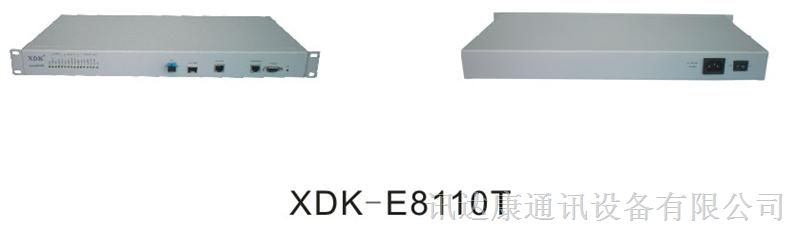
XDK―E8110T
User’s Manual
Company: Shenzhen XDK communication equipment Co., Ltd
Address: No.15 Building. Longbi industrial area, Bantian, BujiTown,Shenzhen,China.
:+86-,,
Fax: 86-
E-mail:
Website:https://www.szxdk.com Postalcode:518129
Contents
Chapter 1: Product introduction
1. Goods listing
2. Front panel instruction
3. Back panel instruction
4. Indication light instruction
5. Main feature
6. Technology
Chapter 2: Installation and link
1. Attention items for setting
Chapter 3: software upgrade
1. Preparation
2. Means and process
Chapter 4: software upgrade
Chapter 1: Product introduction
1. Goods listing
Open the package of fast Ethernet switch, and it contains the following:
A set of OLT, A power supply, a user’s manual and a stream line.
Please contact with supplier if above product and accessory is missing or damaged.
2. Front panel instruction
Front panel of OLT have a power supply jack and a switch button, as the following picture
3. Back panel instruction:
Back panel of ONU from left to right in turn is 16 kinds of status indicators,a PON Port, fiber port, two RJ45 Ports, a bunch port, a replacement switch and a power supply jack, as following illustrate.
4. Indication light instruction
The signification of indicator from left to right is as following:
LED
Color
Status
Description
POW
Green
On
the indicator will light when OLT is opened.
―
Off
Checking the power or power supply adaptor, make sure power supply has connected well.
CRAFT
LINK/ACT
Green
On
Light when equipment normally connect with 100Mbps OLT port
Green
Glitter
Glitter when the port receive or transfer data
100M
Green
On
Corresponding indicator is on when 100Mbps equipment connect with relevant port.
―
Off
Be off when 100Mbps port does not joint equipment.
DUPLEX
Green
On
Be on when port is working base on full duplex mode
―
Off
Be off when port is working base on half duplex mode
ANE/COL
Green
Glitter
Collision happens base on half duplex mode。
―
Off
Normal work status.
LOCAL
LEDTX
Green
On
Be on when the 1000Mbps port is transferring datas.
―
Off
Be off when the 1000Mbps port has no data to transfer.
LEDRX
Green
On
Be on when the 1000Mbps port is receiving datas.
―
Off
Be off when the 1000Mbps port has no data to receive.
LINK1000
Green
On
Be on when 1000Mbps equipment connects with relevant port.
―
Off
Be off when 1000Mbps port does not joint relevant equipment.
LINK100
Green
On
Be on when 100Mbps equipment connects with relevant port.
―
Off
Be off when the port does not joint 100Mbps equipment.
STATUS
ALARM1
Green
Glitter
There will be one ONU or OLT alarm。
―
Off
Normal work status
ALARM2
Green
Glitter
There will be one ONU or OLT alarm。
―
Off
Normal work status
ALARM3
Green
Glitter
There will be one ONU or OLT alarm。
―
Off
Normal work status
ALARM4
Green
Glitter
There will be one ONU or OLT alarm。
―
Off
Normal work status
OPT FAIL
Green
Glitter
The link to the switch fiber port is failing.
―
Off
The link to the switch fiber port is normal
SYS FAIL
Green
Glitter
The link to the local 1000Mbps port is failing.
―
Off
The link to the local 1000Mbps port is normal.
RST
Green
After pressing RST button down,that RST indicator glitters one time means the replacement of the switch.
5. Main feature:
XDK-E8110T,as a new generation of minitype GEPON equipment, is a kind of ecom FTTH bandwidth connecting equipment supplied for ecommunication dealer。Perfect integration, applied flexibility, high reliability, managing, free expansibility, group web and QoS guarantee are its features. XDK-E8110T integrates EPON system based on the IEEE802.3ah new standard,the fiber speed of upstream and downstream can be up to 1.25Gb/s。Each EPON system is available for max 1:32 WDM to transmit datas based on forming fiber web by fiber and 32 EPONlong-distance ON equipments, with great capacity , excellent secrecy, web-grouping flexibility and saving the line resources and the quantity of end equipments。
XDK-E8110T , mainly used for FTTH project,make fiber to household come true, available for Ipephone 、bandwidth datas, operating IPTV, etc;also manage the performance ,failure and deploy. It can be put in ecommunication office or flat, building. If the web is simple, collect it to the central equipment directlly, without per collection。
Characteristics:
● Compatibility
XDK-E8110T is a mini-box-type equipment,only 1U height, can joint XDK-E8010U/XDK-E8011U EPON ONU.
● Long-distance
It is up to 20kms,and can save the cost of web-room construction and maintenance for ecommunication dealer, as it is passive accessories。
● High reliability
Recover after equipment regroups and the power interrupts unconventionally,the system can come back to normal work quickly as the storage scheme.
● Web-grouping flexibility
The up interface of XDK-E8110T can supply 10/100/1000M self-adjustable TX, 1000M FX and different kinds of web-group structure, such as chain-type, star-type, tree-type。
● Full QoS guarantee
Each PON supports up to 256 logic accesses,and single ONU can support many separate logic accesses .For good Qos,it can adopt AES-128 encryption for each access, and supports strong DBA,with powerful bandwidth sharing ability ,flexible bandwidth management and increasing bandwidth using rate effectively; The double managing mode based on SLA and PRI can ensure the users` mini bandwidth demand and low time-delay requirement for the PRI operation。
●Great OAM characteristic
XDK-E8110T supports many operating and manageable ecom characteristics ,such as ONU auto-detection, auto-registration,testing user connection, binding MAC address and filtration, IP address binding and filtration、bandwidth control、VLAN (based on two divisiory means of port and 802.1Q)、flow control、port aggregation, port mirror and broadcast control.
Technical Parameter:
Standard Compliance : IEEE 802.3ah、IEEE 802.3、IEEE 802.3u、IEEE 802.3x、IEEE 802.3z 、IEEE 802.1d、IEEE 802.1p、IEEE 802.1q、IEEE 802.1x、RFC1155、RFC1157、RFC1112、RFC1113 and so on.
● back board exchange capacity:16G
● adjustment capacity:1Kbps
● supporting 4K VLAN based on802.1q,and even 8 K MAC addresses.
Physics feature
●Physics dimension (L440 x W207 x H43, unit: mm)
● frame:19inches,1U height
●Power supply:-48V distributing DC(wave range is-40V~-57V)or 100V~240 V AC
●Weight:4.3kg
●Power consumption:15W
●Temperature:
Operating temperature:0~50℃
Storage temperature:-30~60℃
Relative humidity:10~90% (no coagulation)
Chapter 2: Installation and link
1. Attention item for setting
Please insure that there is suitable work environment and enough free space before installing machine. Please note the installing requirement as following:
●Power supply requirement: 100v-240v AC, the distance between power supply jack and equipment should be within 1.8m.
●Machine should be putted in the ventilated and dry environment, it must leave at least 10cm free space from front to back of machine to airiness
●Insure that around for machine has enough airiness port in order to diffuse quantity of heat, at the same time; don’t put anything heavy on the switch.
Chapter 3:Software introduction
1 Audience
This document is intended for engineers evaluating the TK37XX family of integrated EPON solutions. The document explains how to use the TK37XX PC HOST GUI EponSystemApp.exe, for the purpose of evaluating the functionality and usability of TK37XX Host Interface Protocol. This manual assumes that the reader has a technical background and a base level of understanding regarding the basic operation of PON equipment, but does not assume any prior experience using the TK37XX or any other product. The PC Host GUI is a demonstration package, intended for evaluation purposes only.
2 Organization of the GUI
The screen real estate used by the GUI is divided ― MDI style ― into three sash windows. The upper left panel displays the entities that may be managed by the TK37XX Host Interface, including the OLT, ONUs and Logical Links. This sash window shall be referred to as the Element Status Window. Left clicking on an entity with the mouse will open a tabbed panel in the upper right sash window that may be used to manage the entity. This sash window shall be referred to as the Entity Management Window. The bottommost sash window is used for the purpose of logging the host interface message that are sent and received by the GUI, and shall be referred to as the Message Log. The Message Log displays the commands that are sent and received from the GUI as well as the raw bytes sent and received by the physical layer interface.
2.1 Basic Structure of GUI Software
The GUI software breaks down into 4 logical layers the first layer is the physical interface. The operating system, or driver resource, used to send and receive the raw Host Interface messages. The next layer consists of the underlying messaging system used by the GUI. This layer is responsible for parsing and queuing of Host Interface Messages as well as providing reliability. The next layer is the application layer. This layers responsibility is to display the GUI windows and provide services such as alarm auditing.
2.2 GUI Start Up Sequence
When the user invokes the EponSystemApp.exe by double clicking on the T icon the GUI will perform the following functions:
EponSystemApp.exe
Step 0: Attempt to establish a UDP connection to the TK3721. This process will continue indefiniy or until the connection is established.
Step 1: After the connection is established the GUI will test the interface by attempting to send and receive a host interface message. The natural choice (and the choice that the GUI will use) is the Get OLT Information. This message contains information about the TK3721 that the host may use to identify product version information.
Step 2: Once the interface has been established the next step the GUI shall perform is to obtain the list of discovered links. It should be noted that once the interface is detected the GUI shall initiate a process to handle autonomous events. Receiving an autonomous event will make the remaining sequence non-linear, as the autonomous events will be inserted into the GUIs message queues with other response messages, refer to the note on the GUI data path below.
Step 3: Once the GUI receives this list, it will query the links for the identity of their associated ONUs by issuing a Get ONU Info Host Interface Message for each link found in the list. Of course if an autonomous event (such as link discovery), occurs that event will also be processed simultaneously with the querying process. If the GUI is configured to authenticate its links, the link authentication will also take place. Again there is no set sequence and multiple LLIDs may be authenticated simultaneously.
Step 4: Having discovered the known managed entities the GUI will next query the TK3721 for the list of blocked links. These links will be displayed in the list of unassociated links in the managed entity status window. If the ONU is connected to the TK3721 and operating properly, then unblocking a LLID will cause a new ONU to appear in the entity status window. The LLID will be associated with this new ONU.
Step 5: After the GUI has finished querying the OLT, it will remain in the idle state until the user performs some action. In the idle state the GUI will audit the OLT for alarm messages if configured to do so, otherwise it will not send any Host Interface Messages until the GUI operator directs it to do so, by initiating a query or provisioning action.
2.3 Note on the GUI data Path
The GUIs Data Path consists of simple non-blocking queuing mechanism that achieves very good utilization of OLT recourses. However in such a system there is no set sequence in which messages will be issued to the OLT. Thus that depending on very minor timing differences between command response times, the GUI event log trace will be different. It is important to note that all host interface messages are required to encapsulate a complete set of provisioning operations and therefore do not require that provisioning actions be performed in any set sequence.
3 Basic Operation of the GUI
As stated earlier, left-clicking the mouse on an entity in the Status Window shall cause an associated tabbed dialog to appear in the Management Window. This dialog exposes nearly the entire set of host interface commands associated with the managed entity. The tabs are organized into roughly the same categories as the TK37XX Host Interface document. And with few exceptions all of the panels function similarly.
3.1 GUI Controls All controls in the GUI are derived from a common set of base classes and thus operate in similar ways. Most panels include 1 or two buttons that invoke the GUI to perform various transactions with the OLT. All such controls having the same basic function will also be given the same label. For simplicity of understanding an explanation of each button type appears bellow.
3.1.1 Apply Button
Most GUI panels manage only a single TK3721 Host Interface message. Every time the panel is displayed the GUI will automatically query the OLT for the latest attributes by issuing the appropriate Host Interface Message to the TK3721 firmware. If the query operation is successful the panel will be updated with the latest values from the firmware. As a general rule, when the panel is updated from a host interface message the associated Apply button will be disabled to indicate that the values displayed are an accurate reflection of the current state of the managed entity associated with the panel. If an error occurs the Apply button will not be disabled indicating that the displayed values are not those of the managed entity. Changing a GUI widgets value will cause the Apply button to be enabled allowing the GUI operator to apply the new provisioning to the managed entity.
3.1.2 Refresh Button
Button’s labeled refresh are never disabled. The action associated with a Refresh button is always to query the state of the associated attribute. The result of a successful Refresh operation will be the same as if the panel is viewed for the first time. That is, the OLT will query the managed entity associated with the panel, and if the operation completes the Apply Button will be disabled.
3.1.3 Revert Button
The Revert Button had identical functionality to the Refresh button, but is semantically different. The idea behind the Revert Button is that you can “revert” the panel’s state to the initial state of the panel prior to changing a GUI widget. Semantically, once the apply button has been pressed it is not possible to revert. The Revert Buttons are currently being phased out in favor of the Refresh Button.
3.1.4 Defaults Button
The Defaults Button is used to restore the managed entity to the default settings found in the Host Interface document. This mechanism employs a “canned” Host Interface Message that will be issued to the OLT when the button action is invoked by left clicking on the button.
For most commands a provisioning operation will also result in a subsequent query. In such cases the Apply Button will not be disabled until the query operation completes. This audit mechanism ensures that the values displayed by the panel are the same values stored in the relevant managed entity. For a few Host Interface Messages the granularity of the data is less than that of the provisioned value.
Some Apply actions result in multiple commands being issued to the OLT.
4 GUI Panel Directory
This section describes the various panels found in the GUI, their function, and the method by which they may be used to test the TK37XX Host Interface. The Panels are organized by entity and generally follow the order in which they appear in the associated tabbed dialog box. In the rare case that the GUI abstracts some detail of the host interface, a flow chart of the message exchange sequence is presented. Where the message performs a complex operation on the PON a related diagram may be present as a visual aid. Most panels are subdivided into boxes with each box controlling exactly one host interface message. In most cases the attributes are presented in the same order (as read from top to bottom) as that in which they appear in the Host Interface Message. Thus for the most part the remainder of this document is simply a rehashing of the descriptions already available in the Host Interface Document.
Force link rediscovery de-registers a Logical Link, while allowing it to re-register, as if it had been newly attached to the EPON network. This command is useful, for example, when the Network operator wants to be able to force a re-arrival as part of their debugging process to try to clear a problem, or to re-authenticate the user/ONU on that link.
The Block Link command prevents the given Logical Link (MAC address) from registering on the EPON. The OLT will simply ignore registration requests from the blocked ONU. If the given ONU is already registered, the Logical Link will be deregistered, causing the ONU to depart from the network. All further requests to register from the ONU are ignored until the Host issues an Unblock Link command.
Up to 256 ONU labels (MAC addresses) can be on the block list at one time.
Link blocking is intended to be a temporary measure used to suspend service for reasons such as late payments or a troublesome customer. When the issue has been resolved, or the ONU has been physically removed from the network and no longer requests service, it can be removed from the blocked list with the Unblock Link command. If the ONU is still connected to the network and attempting to register, the ONU will be once again allowed onto the network.
Service provisioning such as SLAs or Bridging modes are not affected by the Block Link command. Any ONU provisioning should be deleted with the appropriate other commands, if desired. A blocked link will appear with a black status icon.
Please note the difference in the behavior with respect to the Block Link command where an Unblock Link is required to undo its effect. Link Rediscovery invites the ONU to re-register this link with the network, while Block Link prevents the ONU from returning on that link after deregistration.
5 OLT Panel
The OLT panel is used to apply settings to OLT attributes. In some cases this may also involve OAM
transactions with ONUs. It should be noted that certain attributes of the OLT such as SLAs are controlled
via the Link Panel.
6 OLT Network Parameters These commands allow the host to configure the way the PON will be managed.
6.1 OAM Rate
This command is used to view the default OAM rate
6.2 Loopback Timeout Value
This sets the loopback failsafe timer. If the operator sets a port in loopback mode the loopback the OLT will initiate a count down timer for Loopback Timeout Value ms. When the timer expires the loopback will automatically be canceled.
6.3 MPCP Parameters
6.3.1 Period
The interval at which the OLT will issue a discovery gate.
6.3.2 Window
The discovery window size in bytes.
6.3.3 VLAN Ethertype
This is the Ethertype value that the OLT will use to classify VLAN traffic (default = 0x8100)
7 DBA
The DBA tab allows the user to control virtually every parameter of the TK3721’s highly flexible and efficient Hierarchal Weighted Round Robin DBA algorithm. The DBA algorithm supplied with the OLT is similar to algorithms found in high performance ATM switches and is capable of issuing 4 grants every 282 micro seconds, by far the fastest cycle time of any EPON system deployed today. The TK3721’s DBA can meet 1 ms. Latency requirements for high priority services in a 32 ONU deployment.
7.1 BroadcastSLA
This command is identical to the functionality of the Link SLA Panel except that it is used to provision anSLAfor the broadcast channel, as apposed to a unicast link. This unique feature of the OLT allows the OLT To use its large 40Meg buffer ram to serve the requirements of all ONUs, resulting in a 1:32 cost reduction (assuming 32 ONU deployment).
7.2 Aggregate Shaper
This command lets the Host restrict the bandwidth available to the OLT for user data traffic in each direction. This feature can be used to protect the core network from bursty upstream flows and increase the accuracy ofSLAenforcement. Aggregate bandwidth control can be disabled by setting the parameters to zero; the feature is disabled by default.
For accurate Min SLA enforcement. recommends that the upstream aggregate shaper be provisioned for 50-100Mbps less than the maximum bandwidth of the PON. Typical values are 800-850Mbps.
7.3PriorityRange
The priority range determines how many links may be registered in each priority level. This command should be applied immediay before registering any links, or after links are deregistered using the Disable OLT command. It is a good idea to configure the OLT in strict boot mode, allowing the host software time to apply this command and then explicitly enable the OLT to register links.
The OLT must be disabled prior to applying this command; otherwise the OLT FIFOs will become corrupt. It is recommend that this operation be performed once during the initial bring up of the PON.
7.4 Shaper Drop Down Weights